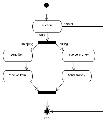
The basis of a process definition is a graph that is made up of nodes and transitions.
That information is expressed in an xml file called processdefinition.xml.
Each node has a type like e.g. state, decision, fork, join,... Each node has a set of leaving
transitions. A name can be given to the transitions that leave a node in order to make them distinct.
For example: The following diagram shows a process graph of the jBAY auction process.
Below is the process graph of the jBAY auction process represented as xml:
<process-definition>

  <start-state>
    <transition to="auction" />
  </start-state>

  <state name="auction">
    <transition name="auction ends" to="salefork" />
    <transition name="cancel" to="end" />
  </state>

  <fork name="salefork">
    <transition name="shipping" to="send item" />
    <transition name="billing" to="receive money" />
  </fork>

  <state name="send item">
    <transition to="receive item" />
  </state>

  <state name="receive item">
    <transition to="salejoin" />
  </state>

  <state name="receive money">
    <transition to="send money" />
  </state>

  <state name="send money">
    <transition to="salejoin" />
  </state>

  <join name="salejoin">
    <transition to="end" />
  </join>

  <end-state name="end" />

</process-definition>