Database description
Overview
Section titled “Overview”The OKMFlow workflow engine uses a relational database to store all workflow-related information. The database schema is organized into two distinct sections:
- Definition Tables: Store the structure and configuration of workflow processes, including nodes, transitions, and their properties
- Execution Tables: Store runtime information about workflow instances, task assignments, process variables, and execution history
This document focuses on the definition tables that describe workflow structure. These tables define the blueprints for workflows that will be executed by the engine.
Database Process Definition Schema Structure
Section titled “Database Process Definition Schema Structure”The definition tables are organized hierarchically with WF_PROCESS_DEFINITION as the root entity. Each process definition contains multiple nodes (WF_NODE) and transitions (WF_TRANSITION) that define the workflow structure. Nodes use inheritance to specialize behavior, while transitions connect nodes to create the workflow execution path.
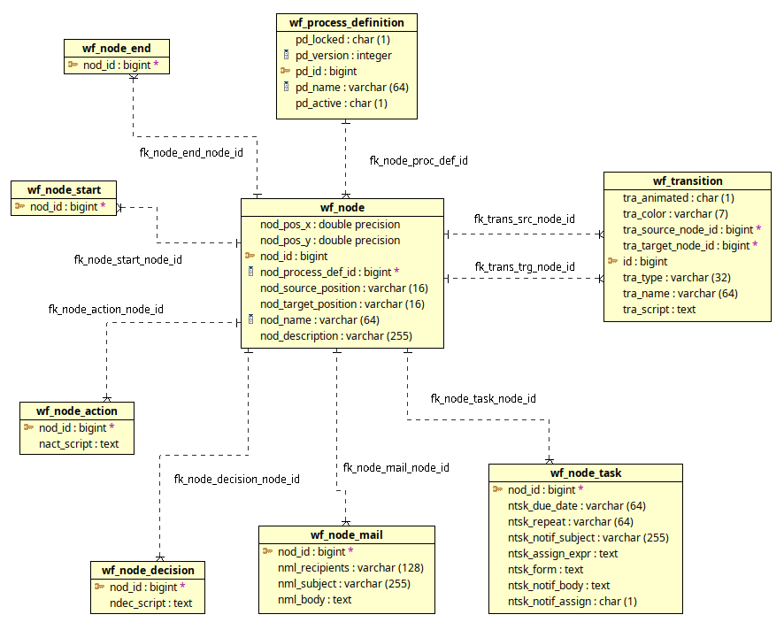
Definition Tables Overview
Section titled “Definition Tables Overview”The following tables store workflow definition information:
| Table | Description |
|---|---|
| WF_PROCESS_DEFINITION | Stores workflow process definitions including name, version, and activation status |
| WF_NODE | Base table for all workflow nodes containing common properties like position, name, and description The wf_node table is the base table for all workflow nodes. This table uses JPA JOINED inheritance strategy, meaning each specialized node type (Start, End, Action, Decision, Mail, Task) has its own table that joins with this base table through a foreign key relationship. |
| WF_NODE_START | Specialized table for Start nodes (inherits from WF_NODE) |
| WF_NODE_END | Specialized table for End nodes (inherits from WF_NODE) |
| WF_NODE_ACTION | Specialized table for Action nodes with script execution capability (inherits from WF_NODE) |
| WF_NODE_DECISION | Specialized table for Decision nodes with conditional routing logic (inherits from WF_NODE) |
| WF_NODE_MAIL | Specialized table for Mail nodes with email sending configuration (inherits from WF_NODE) |
| WF_NODE_TASK | Specialized table for Task nodes with assignment and notification properties (inherits from WF_NODE) |
| WF_TRANSITION | Stores transitions that connect nodes, defining workflow execution paths |
Database Relationships
The definition tables form a hierarchical structure with the following key relationships:
- WF_PROCESS_DEFINITION → WF_NODE: One-to-many relationship. Each process definition contains multiple nodes that define the workflow structure.
- WF_NODE → Specialized Node Tables: JOINED inheritance relationship. Each node type (Start, End, Action, Decision, Mail, Task) extends the base WF_NODE table through a foreign key join.
- WF_NODE → WF_TRANSITION (source): One-to-many relationship. A node can have multiple outgoing transitions.
- WF_NODE → WF_TRANSITION (target): One-to-many relationship. A node can have multiple incoming transitions.
Querying Definition Tables
Section titled “Querying Definition Tables”List All Active Process Definitions
Section titled “List All Active Process Definitions”SELECT PD_ID, PD_NAME, PD_VERSION, PD_ACTIVE FROM WF_PROCESS_DEFINITION WHERE PD_ACTIVE = 'T' ORDER BY PD_NAME, PD_VERSION;Find All Nodes in a Specific Process
Section titled “Find All Nodes in a Specific Process”SELECT n.NOD_ID, n.NOD_NAME, n.NOD_POS_X, n.NOD_POS_Y FROM WF_NODE n INNER JOIN WF_PROCESS_DEFINITION p ON n.NOD_PROCESS_DEF_ID = p.PD_ID WHERE p.PD_NAME = 'document_approval' ORDER BY n.NOD_NAME;List All Task Nodes with Notification Settings
Section titled “List All Task Nodes with Notification Settings”SELECT n.NOD_ID, n.NOD_NAME, t.NTSK_NOTIF_ASSIGN, t.NTSK_NOTIF_SUBJECT FROM WF_NODE n INNER JOIN WF_NODE_TASK t ON n.NOD_ID = t.NOD_ID WHERE t.NTSK_NOTIF_ASSIGN = 'T';Find Transitions Between Specific Nodes
Section titled “Find Transitions Between Specific Nodes”SELECT t.ID, t.TRA_NAME, t.TRA_TYPE, ns.NOD_NAME AS SOURCE_NODE, nt.NOD_NAME AS TARGET_NODE FROM WF_TRANSITION t INNER JOIN WF_NODE ns ON t.TRA_SOURCE_NODE_ID = ns.NOD_ID INNER JOIN WF_NODE nt ON t.TRA_TARGET_NODE_ID = nt.NOD_ID;Count Nodes by Type in a Process
Section titled “Count Nodes by Type in a Process”-- Count Start nodesSELECT COUNT(*) AS START_NODES FROM WF_NODE n INNER JOIN WF_NODE_START s ON n.NOD_ID = s.NOD_ID WHERE n.NOD_PROCESS_DEF_ID = 1;
-- Count Task nodesSELECT COUNT(*) AS TASK_NODES FROM WF_NODE n INNER JOIN WF_NODE_TASK t ON n.NOD_ID = t.NOD_ID WHERE n.NOD_PROCESS_DEF_ID = 1;
-- Count Decision nodesSELECT COUNT(*) AS DECISION_NODES FROM WF_NODE n INNER JOIN WF_NODE_DECISION d ON n.NOD_ID = d.NOD_ID WHERE n.NOD_PROCESS_DEF_ID = 1Database Process Execution Schema Structure
Section titled “Database Process Execution Schema Structure”The execution tables track the runtime state of workflow instances as they execute. These tables capture process instances, task assignments, variables, and execution history, forming a complete audit trail of workflow execution.
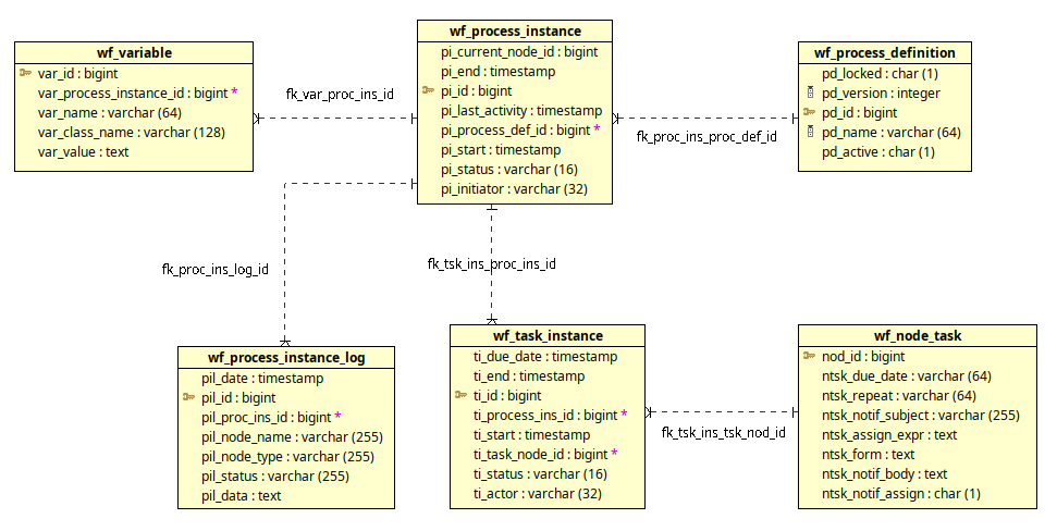
Execution Tables Overview
Section titled “Execution Tables Overview”The following tables store workflow execution information:
| Table | Description |
|---|---|
| WF_PROCESS_INSTANCE | Stores runtime instances of workflow processes, tracking their current state and execution progress |
| WF_TASK_INSTANCE | Stores individual task assignments created during workflow execution, including assignee and completion status The wf_task_instance table includes a collection table wf_task_ins_pooled_actors for storing multiple potential assignees. When a task is configured for pooled assignment, multiple users can claim it, but only one will be assigned when claimed. |
| WF_VARIABLE | Stores process variables that hold data during workflow execution, supporting dynamic workflow behavior |
| WF_PROCESS_INSTANCE_LOG | Stores audit log entries tracking workflow execution history, node transitions, and task events |
Database Relationships
The execution tables form a runtime structure centered around process instances:
- WF_PROCESS_INSTANCE → WF_PROCESS_DEFINITION: Many-to-one relationship. Each process instance is created from a specific process definition version.
- WF_PROCESS_INSTANCE → WF_NODE: Many-to-one relationship. Tracks the current node where the workflow execution is positioned.
- WF_PROCESS_INSTANCE → WF_TASK_INSTANCE: One-to-many relationship. A process instance generates multiple task instances as it executes.
- WF_PROCESS_INSTANCE → WF_VARIABLE: One-to-many relationship. Each process instance maintains its own set of variables.
- WF_PROCESS_INSTANCE → WF_PROCESS_INSTANCE_LOG: One-to-many relationship. Process execution generates multiple log entries tracking its history.
- WF_TASK_INSTANCE → WF_NODE_TASK: Many-to-one relationship. Each task instance is created from a task node definition.
Querying Execution Tables
Section titled “Querying Execution Tables”Find Running Process Instances
Section titled “Find Running Process Instances”SELECT pi.PI_ID, pd.PD_NAME, pi.PI_STATUS, pi.PI_INITIATOR, pi.PI_START FROM WF_PROCESS_INSTANCE pi INNER JOIN WF_PROCESS_DEFINITION pd ON pi.PI_PROCESS_DEF_ID = pd.PD_ID WHERE pi.PI_STATUS = 'running' ORDER BY pi.PI_START DESC;Find All Tasks Assigned to a User
Section titled “Find All Tasks Assigned to a User”SELECT ti.TI_ID, ti.TI_STATUS, ti.TI_DUE_DATE, pi.PI_ID AS PROCESS_ID, pd.PD_NAME AS PROCESS_NAME FROM WF_TASK_INSTANCE ti INNER JOIN WF_PROCESS_INSTANCE pi ON ti.TI_PROCESS_INS_ID = pi.PI_ID INNER JOIN WF_PROCESS_DEFINITION pd ON pi.PI_PROCESS_DEF_ID = pd.PD_ID WHERE ti.TI_ACTOR = 'jsmith' AND ti.TI_STATUS IN ('open', 'assigned') ORDER BY ti.TI_DUE_DATE;List Process Variables for an Instance
Section titled “List Process Variables for an Instance”SELECT VAR_NAME, VAR_CLASS_NAME, VAR_VALUE FROM WF_VARIABLE WHERE VAR_PROCESS_INSTANCE_ID = 123 ORDER BY VAR_NAME;View Execution History for a Process Instance
Section titled “View Execution History for a Process Instance”SELECT PIL_DATE, PIL_NODE_TYPE, PIL_NODE_NAME, PIL_STATUS, PIL_DATA FROM WF_PROCESS_INSTANCE_LOG WHERE PIL_PROC_INS_ID = 123 ORDER BY PIL_DATE ASC;